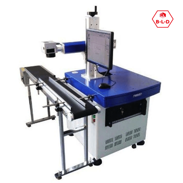
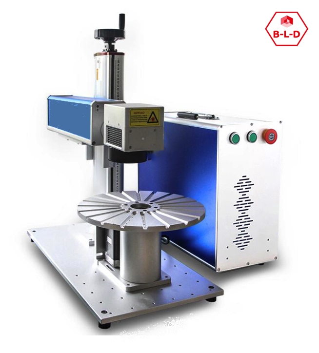
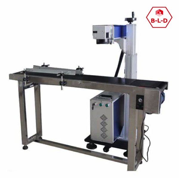
When using a CCD vision system for automatic part identification, there are several parameters that may require adjustments at each part change to ensure accurate recognition, this results in small and different batches being time and resource consuming. Here are some of the common parameters that may need to be adjusted at change of use:
Region of Interest (ROI): The region of interest indicates the area of the image where the CCD system searches for part details. It is important to adjust this area to match the size and location of the specific part.
Brightness/Contrast: Depending on the color and reflectivity of the part, the brightness and contrast levels of the image can affect the ability of the recognition system. It may be necessary to adjust these parameters to obtain clear and detailed images.
Thresholding: Thresholding is the process of converting the grayscale image to a binary image, where objects to be identified are clearly distinguished. The choice of thresholding value may vary depending on the part and may require adjustments.
Noise Filter: The scanned image may contain unwanted noise or detail. The application of noise reduction filters may be necessary to improve viewing accuracy.
Recognition Algorithm: The algorithm used for part recognition may require adjustments to handle specific shapes, colors, or details depending on the part in question.
Angle and Rotation: If the workpiece may vary in angle or rotation, parameters may need to be adjusted to ensure accurate recognition in different positions.
Piece Size: Limits on piece size can be set to exclude objects that are too large or too small from the identification process.
Environmental Lighting: Changes in environmental brightness can affect image quality. Adaptable or adjustable lighting systems may be useful.
Each part change may require evaluation and adjustment of these parameters to ensure that the CCD system can correctly and reliably identify the new part.
The cost-effectiveness given the need to still have an operator loading the parts, random or aligned, and the time required to change printing parameters will have to be evaluated. Loghil allotment or other common for both l;e configurations.
Added to which is the CCD setting described above in that each part must be focused for the CCD system to do exactly the job required.
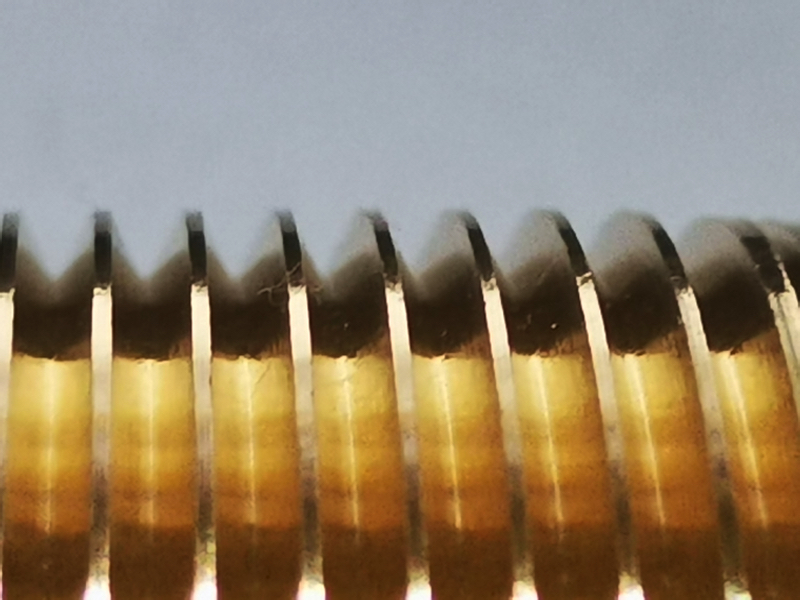
Incorrect adjustment can result in a number of parts that are not properly identified and marked