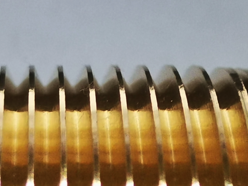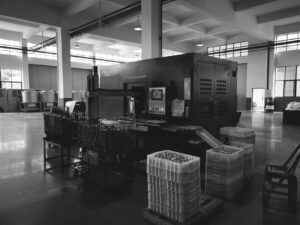
Laser Marking Machine for PPR Components and Similar Materials
Introducing our innovative laser marking solution for small parts made of PPR and other materials. Our application combines advanced technology and ease of use to deliver accurate and durable results.
## Main Features:
–**Advanced Structure:** Our marking machine consists of a laser beam emitting device and a conveyor belt. This configuration enables efficient marking of moving components.
–**Intuitive Management:** The laser beam management system allows predefined sequences to be set up easily and intuitively, similar to the use of common graphics programs on computers.
–**Material Versatility:** The marker is capable of marking on a wide range of materials, including paper, steel, brass, plastics, and, in particular, the durable PPR commonly used in plumbing.
The laser marking machine described here is a device that uses a laser beam to perform marking on parts that are brought into the laser beam’s area of action by a conveyor belt. With or without alignment slides. The operation of this marking machine is based on the control of a photocell, which detects the passage of workpieces in front of the marking machine.
When the workpieces flow past the photocell, the signal generated by the activation of the photocell excites the laser marker. This means that the laser is turned on and ready to perform printing on the surface of the workpiece.
At the moment the laser is activated, the laser beam cuts with times of 3 to 9 tenths of a second for lettering or linear codes, up to a few seconds for more complex figures. During this short time interval, the laser control system performs pre-loaded printing, which is programmed in advance through an easy-to-use control application.
The executions
The video illustrates some examples in operation

Laser Marking Process on OSR
- **Engraving Marking:** High-intensity laser beam melts or burns the surface layer of PPR, creating a permanent engraving.
- **Color Change:** Some pigments in PPR react to heat, changing color without damaging the surface.
- **Color Removal:** A laser beam removes a thin layer of the PPR surface, creating a marking without significant damage.
## Marker Operation:
The marking machine uses a photocell to detect the passage of parts into the engraving area reflected on the conveyor belt. When the parts activate the photocell, the laser starts to perform marking with times of 0.3-0.8 seconds. In case of longer marking, the belt stops the time needed for the beam and resumes after marking.
Digital communication between the conveyor belt and laser, managed by an encoder, ensures synchronized and precise operation. The large printing area (approximately 130×180 mm) is adjustable via a control application.

Advanced solution with CCD video scanner
The laser marking system is operated by a galvanometer, (the apparatus that through lenses directs the laser beam in different directions so as to compose text and graphic shapes) identification of parts is done through the use of a CCD (Charge-Coupled Device) viewer. Here is how the process of identifying and aligning parts for marking works:
- Image Acquisition: The CCD viewer captures a real-time image of the transit area of the parts. This device is able to perceive shapes and contours of the parts due to its ability to translate light into electronic signals.
- Shape Analysis: The software associated with the CCD viewer analyzes the captured image to identify the shape and position of the parts. This process of shape analysis enables the system to recognize and distinguish different types of parts, even when they are transiting in a haphazard manner.
- Command to Galvanometer: Once the shape of the part has been identified, the software sends instructions to the laser marker’s galvanometer system. These instructions include the exact position, direction and inclination required to make the desired mark on the part.
- Dynamic Alignment: During part transit, the control system dynamically adjusts the instructions sent to the galvanometer to correctly align each part under the printing area. This process occurs in real time, allowing accurate marking even if the parts are randomly arranged.
- Marking: Once correctly aligned, the galvanometer-controlled laser performs marking on the surface of the part. The marking can include text, codes, symbols or other desired information.
This identification and alignment methodology allows the laser marker to handle randomly flowing parts without a pre-determined order. The use of the CCD viewer and galvanometer enables precise and flexible marking on different types of parts, improving the efficiency of the marking process.
CCD Vision
Video illustrates operation vision and part identification with CCD

Some combinations dimarking laser sunastro conveyor with random scattered pieces identified emarked by CCD system
Advanced solution with CCD video scanner
When using a CCD vision system for automatic part identification, there are several parameters that may require adjustments at each part change to ensure accurate recognition, this results in small and different batches being time and resource consuming. Here are some of the common parameters that may need to be adjusted at change of use:
Region of Interest (ROI): The region of interest indicates the area of the image where the CCD system searches for part details. It is important to adjust this area to match the size and location of the specific part.
Brightness/Contrast: Depending on the color and reflectivity of the part, the brightness and contrast levels of the image can affect the ability of the recognition system. It may be necessary to adjust these parameters to obtain clear and detailed images.
Thresholding: Thresholding is the process of converting the grayscale image to a binary image, where objects to be identified are clearly distinguished. The choice of thresholding value may vary depending on the part and may require adjustments.
Noise Filter: The scanned image may contain unwanted noise or detail. The application of noise reduction filters may be necessary to improve viewing accuracy.
Recognition Algorithm: The algorithm used for part recognition may require adjustments to handle specific shapes, colors, or details depending on the part in question.
Angle and Rotation: If the workpiece may vary in angle or rotation, parameters may need to be adjusted to ensure accurate recognition in different positions.
Piece Size: Limits on piece size can be set to exclude objects that are too large or too small from the identification process.
Environmental Lighting: Changes in environmental brightness can affect image quality. Adaptable or adjustable lighting systems may be useful.
Each part change may require evaluation and adjustment of these parameters to ensure that the CCD system can correctly and reliably identify the new part.
Important Note
When using a CCD vision system for automatic part identification, there are several parameters that may require adjustments at each part change to ensure accurate recognition, this results in small and different batches being time and resource consuming. Here are some of the common parameters that may need to be adjusted at change of use:
Region of Interest (ROI): The region of interest indicates the area of the image where the CCD system searches for part details. It is important to adjust this area to match the size and location of the specific part.
Brightness/Contrast: Depending on the color and reflectivity of the part, the brightness and contrast levels of the image can affect the ability of the recognition system. It may be necessary to adjust these parameters to obtain clear and detailed images.
Thresholding: Thresholding is the process of converting the grayscale image to a binary image, where objects to be identified are clearly distinguished. The choice of thresholding value may vary depending on the part and may require adjustments.
Noise Filter: The scanned image may contain unwanted noise or detail. The application of noise reduction filters may be necessary to improve viewing accuracy.
Recognition Algorithm: The algorithm used for part recognition may require adjustments to handle specific shapes, colors, or details depending on the part in question.
Angle and Rotation: If the workpiece may vary in angle or rotation, parameters may need to be adjusted to ensure accurate recognition in different positions.
Piece Size: Limits on piece size can be set to exclude objects that are too large or too small from the identification process.
Environmental Lighting: Changes in environmental brightness can affect image quality. Adaptable or adjustable lighting systems may be useful.
Each part change may require evaluation and adjustment of these parameters to ensure that the CCD system can correctly and reliably identify the new part.
The cost-effectiveness given the need to still have an operator loading the parts, random or aligned, and the time required to change printing parameters will have to be evaluated. Loghil allotment or other common for both l;e configurations.
Added to which is the CCD setting described above in that each part must be focused for the CCD system to do exactly the job required.
Incorrect adjustment can result in a number of parts that are not properly identified and marked
Advantages of Laser Marking
–**Precision:** Detailed results on different materials.
–**Speed:** Fast marking due to synchronization with the conveyor belt.
–**Flexibility:** Adaptable to different sizes and types of materials.
–**Automation:** Predefined programming options for efficient production.
Choose our laser marking machine for advanced and reliable marking on PPR parts and other materials. Further automation and customization are possible.
It will be the customer’s responsibility to ask for machines with or without required safety devices in the lugo of installation and use.
Our machine doing great job at www.nptmetalchina.com
Trusted By
Who we've worked and we are working with


Nomi e loghi di alcuni nostri clienti illustrati sul sito sono esclusi dalla pubblicazione in ottemperanza agli accordi di riservatezza e per tutelare la confidenzialità industriale.
B-L-D About Us
30 years of international experience in thermo-hydraulics and related fields


Belinda
Zhang
Direttore

Daniele
Prandelli
Consulente

Helen
Hoffman
Direttore operativo

Cesare
Tomasoni
Coordinamento Italia
© bei-lin-da.com 2024 All Rights Reserved.


